
High Power Laser Turret
The high power laser (HPL) was the first major project I undertook as a hobby, and it required me to learn skills such as power supply design, optics, 3D modeling, mechatronics, software, and above all else, safety.
I undertook this project after my first summer internship enabled me to acquire more exotic components (AKA I had disposable income for the first time). I had been a big fan of creators such as Styropyro, and once I had the means I set to work searching on eBay for listings for the same or similar high power laser arrays as he used. Eventually, I found a international vendor and was able to negotiate a discount, on account of me being a student, and the promise that I would purchase more laser arrays, which I did.
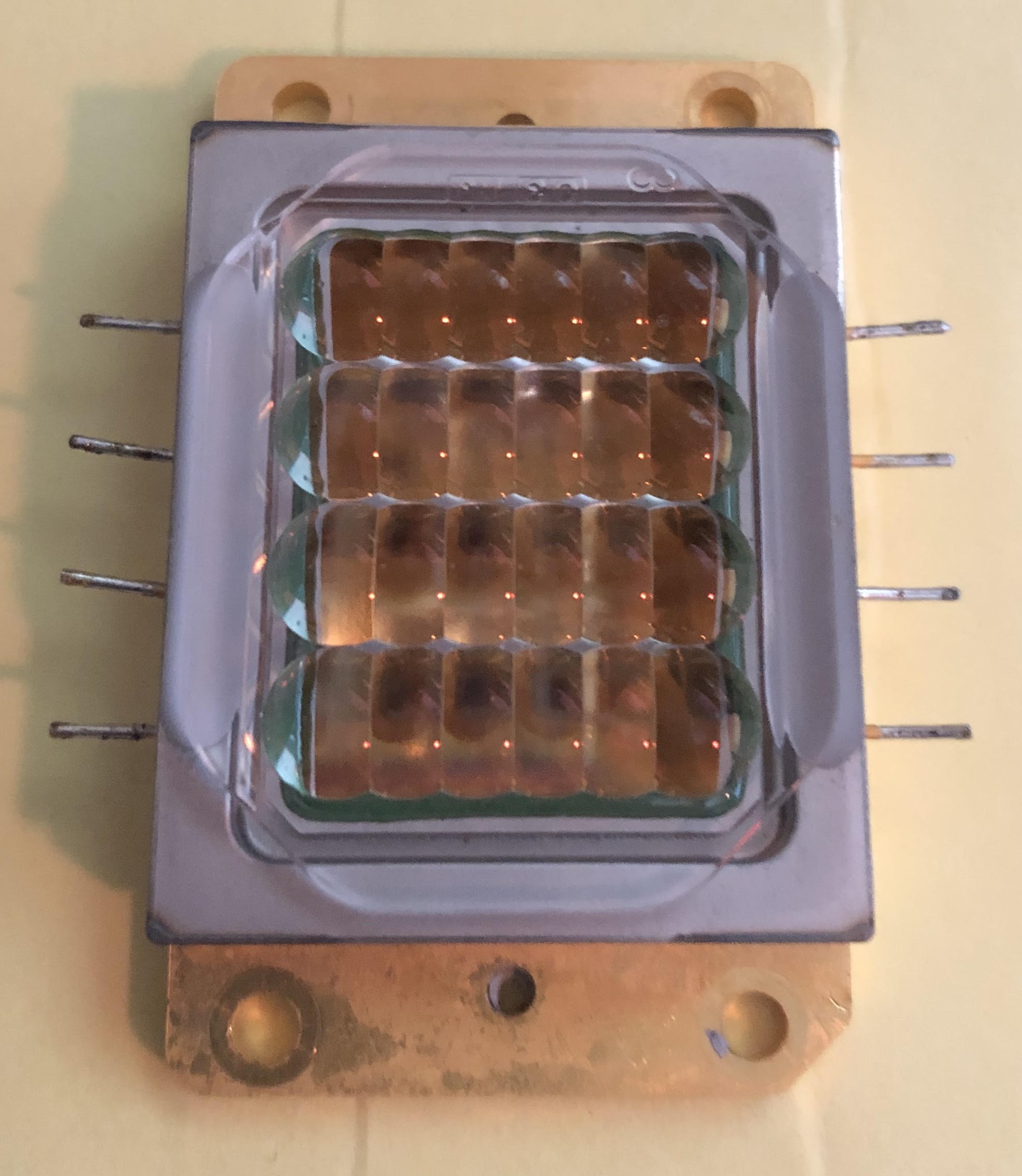
Once I got the laser arrays, my first problem was reverse engineering the wiring diagram, as the array did not come with an adequate schematic. I was able to use a multimeter on its continuity setting to get the schematic, and I was able to move onto my next problem: power.
You see, lasers, while thought of by most to be some futuristic technology, are in fact, rather simple. In this case specifically, since the laser was 450nm (blue) laser diode, it behaved almost exactly as a normal LED (Light Emitting Diode) would. This, of course, meant that the laser was a current mode device, and needed a power source with precise current control, as a small variation in the voltage supply would produce drastic changes in output power, and potentially destroy the laser diode. The following image will help me explain this:
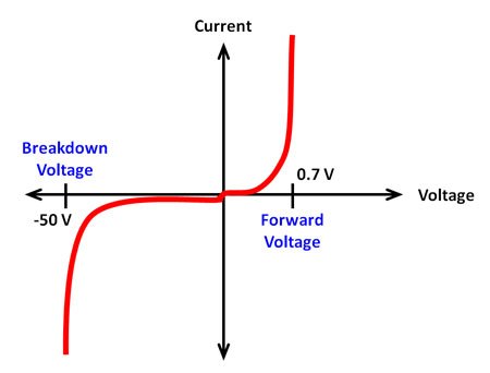
Looking at this figure, which is the IV (Current/Voltage) curve of a common rectifier diode, we can begin to understand the behavior of diodes or diode-like devices, such as the laser array. 1st off, notice that very little current flows if the voltage polarity is negative. This is because diodes operate like 1-way valves, they allow current to flow easily in one direction, and strongly oppose flow in the opposite direction. This means that the polarity of the power supply is important and must be kept in mind. Next, we can see that as we increase the voltage past zero, very little current flows until we reach a 0.7V, at which a massive spike in current flow is observed. This point, which for common rectifier diodes is 0.7V, is called a threshold voltage. Our laser diode also has a threshold voltage, and it is important to know, as the threshold voltage multiplied by the current flowing through the device will give you the power dissipated as heat, which will need be managed with an active cooling system. Less waste heat is better. The main problem here is that we need a way to control the intensity of the laser, but looking at that graph you may think we have 2 possible states, those being fully on and fully off.
My array is comprised of 6 elements per row, with 4 rows, for a total of 24 lasers. The threshold voltage of each diode is 5V, thus making the threshold of each row 30V. Additionally, the current flow in each row will be 3.5A minimum. This means I need a power source that is 30V and able to source 14A without exploding. Oh, and the power source is a 7.4V lipo battery. We will come back to how a 7.4V battery is meant to supply 30V.
Luckily, we are not the first people to ever run into the issue of controlling the power output of a diode device, as I would bet that your home has some type of LED dimmer, which can change the intensity of your LED lights. Those systems and the system I produced are identical, and how they work is clever. May I introduce you to the amazing world of pulse width modulation (PWM)!
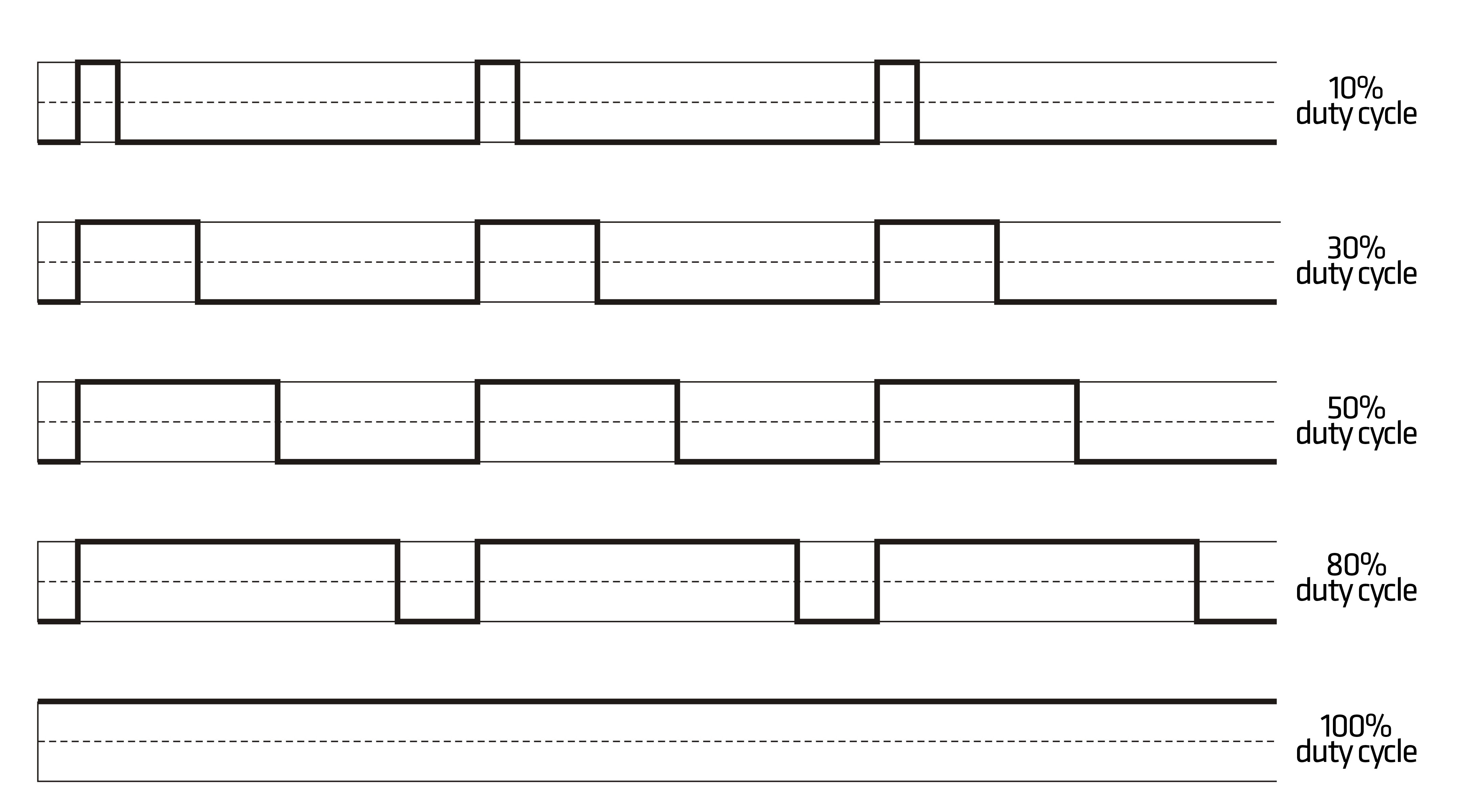
Looking at this figure, I need to introduce some terminology. First, the plots are of an arbitrary signal, and the x-axis is time in this case, with the y axis being magnitude of the signal, but we can just call it Volts for now. A very important concept to signals is that of period and frequency. These quantities are inversely proportional to one another, that is, period is equal to 1/frequency, and vice versa. period is how long something takes to repeat. think of a steady drumbeat, where a drummer strikes the drum 1 time a second. The period of the drum strikes would be 1 second long, that is, it takes 1 second of time between each drum strike. Signals that have a defined period are known as periodic. Using the same drum example, and the fact we know the 1/period is equal to the frequency, we can say the drumbeat has a frequency of 1 Hz, where Hz is Hertz, the unit of frequency, also known as 1/seconds. now that we have established some basic signal concepts, we can begin to breakdown the idea of PWM.
PWM is when a periodic signal’s on time is modified, such that the signal spends more or less time on in a given period. Looking at the figure, a higher on time, also known as a duty cycle, results in the signal being in the on state for a large percentage of the period. that means if a duty cycle is 75%, then the signal spends 3/4 of its period in the on state. using this digital technique, we can effectively turn our laser on and off fast, and we can leave it on longer or shorter, thereby increasing or decreasing our total power output.